SAI – Safety analog input
Block SymbolLicensing group: ADVANCED

Function Description
The SAI block tests the input signal u and assesses its validity. The input signal u is considered invalid
(the output E=on)
in the following cases:
- F1: Hardware error. The input signal HWF=on.
- F2: The input signal u varies too little. The last nc samples of the input u lies within the
interval of width du,
du=<vmax−vmin2nbits,fornbits∈{8,9,...,16}0,fornbits∉{8,9,...,16},
where vmin and vmax are the lower and upper limits of the input u, respectively, and nbits is the number of A/D converter bits. The situation when the input signal u varies too little is shown in the following picture:
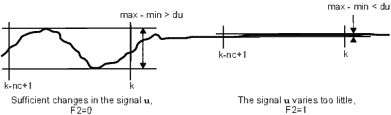
If the parameter nc is set to nc=0, the condition F2 is never fulfilled.
- F3: The input signal u varies too much. The last nr samples of the input u filtered by the
SPIKE filter have a span which is greater than rate,
rate=pratevmax−vmin100,
where prate defines the allowed percentage change in the input signal u within the last nr samples (with respect to the overall range of the input signal u∈⟨vmin,vmax⟩). The block includes a SPIKE filter with fixed parameters mingap=vmax−vmin100 and q=2 suppressing peaks in the input signal to avoid undesirable fulfilling of this condition. See the SPIKE block description for more details. The situation when the input signal u varies too much is shown in the following picture:
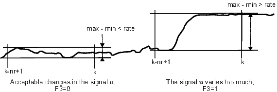
If the parameter nr is set to nr=0, the condition F3 is never fulfilled.
- F4: The input signal u is out of range. The last nv samples of the input signal u lie out of the allowed
range ⟨vmin,vmax⟩.
If the parameter nv is set to nv=0, the condition F4 is never fulfilled.
The signal u is copied to the output y without any modification when it is considered valid. In the other case, the output y is determined by a substitute value from the sv input. In such a case the output E is set to on and the output iE provides the error code. The input R resets the inner error flags F1–F4. For the input R set permanently to on, the invalidity indicator E is set to on for only one cycle period whenever some invalidity condition is fulfilled. On the other hand, for R=off, the output E is set to on and remains true until the reset (rising edge R: off→on).
The table of error codes iE resulting from the inner error flags F1–F4:
| F1 | F2 | F3 | F4 | iE |
| 0 | 0 | 0 | 0 | 0 |
| 0 | 0 | 0 | 1 | 1 |
| 0 | 0 | 1 | 0 | 2 |
| 0 | 0 | 1 | 1 | 3 |
| 0 | 1 | 0 | 0 | 4 |
| 0 | 1 | 0 | 1 | 5 |
| 0 | 1 | 1 | 0 | 6 |
| 0 | 1 | 1 | 1 | 7 |
| 1 | * | * | * | 8 |
The nb parameter defines the number of samples which are not included in the validity assessment after initialization of the block (restart). Recommended setting is nb≥5 to allow the SPIKE filter initial conditions to fade away.
Inputs
u | Analog input of the block | Double (F64) |
sv | Substitute value to be used when the signal u is marked as invalid | Double (F64) |
HWF | Hardware error indicator | Bool |
|
|
|
R | Reset inner error flags F1–F4 | Bool |
Outputs
y | Analog output of the block | Double (F64) |
yf | Filtered analog output signal y, output of the SPIKE filter | Double (F64) |
E | Output signal invalidity indicator | Bool |
|
|
|
iE | Reason of invalidity | Long (I32) |
|
|
|
Parameters
nb | Number of samples which are not included in the validity assessment of the signal u after initialization of the block ⊙10 | Long (I32) |
nc | Number of samples for invariability testing (the F2 condition) ⊙10 | Long (I32) |
nbits | Number of A/D converter bits ⊙12 | Long (I32) |
nr | Number of samples for variability testing (the F3 condition) ⊙10 | Long (I32) |
prate | Maximum allowed percentage change of the input u within the last nr samples (with respect to the overall range of the input signal vmax−vmin) ⊙10.0 | Double (F64) |
nv | Number of samples for out-of-range testing (the F4 condition) ⊙1 | Long (I32) |
vmin | Lower limit for the input signal u ⊙-1.0 | Double (F64) |
vmax | Upper limit for the input signal u ⊙1.0 | Double (F64) |
[Previous] [Back to top] [Up] [Next]
2023 © REX Controls s.r.o., www.rexygen.com