RDC – Remote data connection
Block SymbolLicensing group: ADVANCED

Function Description
The RDC block is a special input-output block. The values are transferred between two blocks on different computers, eventually two different Simulinks on the same computer or Simulink and the REXYGEN system on the same computer. In order to communicate, the two RDC blocks must have the same id number. The communication is based on UDP/IP protocol. This protocol is used as commonly as the more known TCP/IP, i.e. it works over all LAN networks and the Internet. The algorithm performs the following operations in each step:
- If HLD=on, the block execution is terminated.
- If the period parameter is a positive number, the difference between the system timer and the time of the last packet sending is evaluated. The block execution is stopped if the difference does not exceed the period parameter. If the period parameter is zero or negative, the time difference is not checked.
- A data packet is created. The packet includes block number, the so-called invoke number (serial number of the packet) and the values u0 to u15. All values are stored in the commonly used so-called network byte order, therefore the application is computer and/or processor independent.
- The packet is sent to the specified IP address and port.
- The invoke number is increased by 1.
- It is checked whether any incoming packets have been received.
- If so, the packet validity is checked (size, id number, invoke number).
- If the data is valid, all outputs y0 to y15 are set to the values contained in the packet received.
- The fresh output is updated. In case of error, the error code is displayed by the err output.
There are 16 values transmitted in each direction periodically between two blocks with the same id number. The u(i) input of the first block is transmitted the y(i) output of the other block. Unlike the TCP/IP protocol, the UDP/IP protocol does not have any mechanism for dealing with lost or duplicate packets, so it must be handled by the algorithm itself. The invoke number is used for this purpose. This state variable is increased by 1 each time a packet is sent. The block stores also the invoke number of the last received packet. It is possible to distinguish between various events by comparing these two invoke numbers. The packets with invoke numbers lower than the invoke number of the last received packet are denied unless the difference is grater than 10. This solves the situation when one of the RDC blocks is restarted and its invoke number is reset.
All RDC blocks in the same application must have the same local port number and the number of RDC blocks is limited to 64 for implementation reasons. If there are two applications using the RDC block running on the same machine, then each of them must use a different local port number.
Inputs
HLD | Input for disabling the execution of the block. No packets are received nor transmitted when HLD=on. | Bool |
u0..u15 | Values which are sent/written to the output values y0 to y15 of the paired block | Double (F64) |
Outputs
iE | Displays the code of the last error. The error codes are listed below: | Long (I32) |
|
|
|
| Persistent errors originating in the initialization phase (<0). Cannot be fixed automatically. |
|
|
|
|
| Temporary errors originating in any cycle of the code (>0). Can be fixed automatically. |
|
|
|
|
fresh | Elapsed time (in seconds) since the last received packet. Can be used for detection of an error in the paired block. | Double (F64) |
y0..y15 | Values transmitted from the input ports u0 to u15 of the paired RDC block – data from the last packet received | Double (F64) |
Parameters
target | Name or IP address running the paired RDC block. Broadcast address is allowed. | String |
rport | Remote port – address of the UDP/IP protocol service, it is recommended to keep the default value unless necessary (service/application conflict) ⊙1288 | Word (U16) |
lport | Local port – similar meaning as the rport parameter; remote port applies to the receiving machine, local port applies to the machine sending the packet ⊙1288 | Word (U16) |
id | Block ID – this number is contained within the data packet in order to reach the proper target block (all blocks on the target receive the packet but only the one with the corresponding id decomposes it and uses the data contained to update its outputs) ↓1 ↑32767 ⊙1 | Long (I32) |
period | The shortest time interval between transmitting/receiving packets (in seconds). The packets are transmitted/received during each execution of the block for period≤0 while the positive values of this parameter are extremely useful when sending data out of the Simulink continuous models based on a Variable step solver. | Double (F64) |
Example
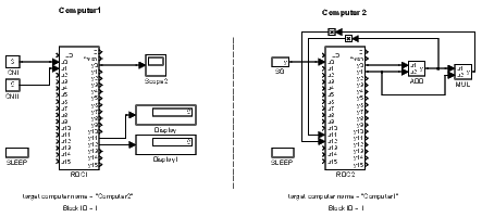
The following example explains the function of the RDC block. The constants 3 and 5 are sent from Computer1 to Computer2, where they appear at the y0 and y1 outputs of the RDC2 block. The constants are then summed and multiplied and sent back to Computer1 via the u11 and u12 outputs of the RDC2 block. The displays connected to the y11 and y12 outputs of the RDC1 block show the results of mathematical operations 3+5 and (3+5)∗5. The signal from the SG generator running on Computer2 is transmitted to the y0 output of the RDC1 block, where it can be easily displayed. Note that Display and Scope are Matlab/Simulink blocks – to view the data in the REXYGEN system, the REXYGEN Diagnostics diagnostic program and the TRND block must be used.

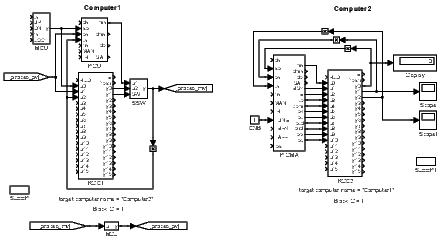
The simplicity of the example is intentional. The goal is to demonstrate the functionality of the block, not the complexity of the system. In reality, the RDC block is used in more complex tasks, e.g. for remote tuning of the PID controller as shown below. The PID control algorithm is running on Computer1 while the tuning algorithm is executed by Computer2. See the PIDU, PIDMA and SSW blocks for more details.

There is also an OPC server embedded in the RDC block. Detailed description will be available soon.
[Previous] [Back to top] [Up] [Next]
2020 © REX Controls s.r.o., www.rexygen.com